How MachineSense Helps You Measure Harmonics in Electrical Lines
Harmonics, the Unknown Assassin of Your Electric Power Line!
You’re saving power by LED and Vector Drives, but…
You have recently upgraded all of the office lights to LEDs in your building, using approximately 50% less electricity than traditional incandescent, fluorescent and halogen options.
You’re confident that this will save you 5-10% of your total utility bills, but you’re also noticing that office laptops don’t last as long they are supposed to. Exhaust fans and HVAC systems have started failing at an alarming rate, while servers are rebooting more frequently in the server room.
You’re probably content with the fact you have installed VFD with many of the processing motors, thus saving electricity, but you never considered placing isolation transformers before the driver. So now you’re noticing many of the machines which have small motors are failing more frequently while PLCs are losing data and constantly rebooting.
The reality is you have introduced a silent assassin in your powerline. In a bid to save power, you’ve actually compromised your powerline with harmonics. And harmonics are the silent killer that can, and will disrupt your power.
In simple terms, harmonics are unwanted frequency components in electrical lines. They are an integral multiple of fundamental carrier frequency. Thus they are 120/180/240 Hz, integral multiple of 60Hz signal. Current Harmonics are more common than voltage harmonics, and most inductive motors, the harmonics part of the power, is dissipated as heat in the motor coils.
Since motors consume a large part of factory loads, higher harmonics in power distribution leads to a significant waste of energy, and thus negatively impacting the operational bottom line. In addition, a heated motor core will degrade faster and fail much earlier than the life cycle warranty.
In the consumer world, with the ubiquitous rise of mobile devices, LED lighting and the explosive growth of IoT, DC power supplies are witnessing exponential growth, especially in commercial buildings and homes, where rectifier diodes of the DC power supplies contribute to the highest source of harmonics.
Imbalanced currents of three phase lines, and vector drives of the motors, also contribute to the high level of harmonics in factories. Basically, any kind of non-linear load will give rise to high harmonic content. Since use of vector drives and DC devices are at alarmingly high levels, IEEE has issued a stringent standard for the utilities to comply with harmonics generation from the devices ( Std. 519-1992).
But that alone doesn’t solve the problem because harmonics are generated inside the factories and the buildings from vector/DC drives and DC power supplies. Everyone is replacing Tungsten lamps with LEDs, but none will add an isolation transformer to arrest the harmonics generated from DC power supplies of the LED. LED saves on electricity bills but unleashes harmonics to cause havoc with power lines. Once a building is retrofitted with new LED lights, laptop power supplies and mobile devices will die faster since harmonic power will be dissipated inside the power convertor.
Exhaust fans, AC compressors, and HVAC will experience more frequent downtime because motors will be dying due to elevated coil temperature. Servers will be resetting/rebooting more often because cooling fans inside the server will suffer premature failure. Office routers will be resetting and frequently losing connections because silicon chips will be losing clocks due to harmonic storms.
Factories are actually the worst affected after adaptation of VFDs. Since harmonics generated from VFD ranges from 20-60%, If this harmonic storm is not filtered or isolated, they will spread throughout the factory like a virus and kill all the healthy motors that do not have a drive.
Have you done a good job in tapping single phaselines from three phase mains?
In general power companies do a good job of maintaining IEEE 519 to keep the current harmonic contents less than 2-4% and feeding a balanced 3-phase supply to building and factories. However, inside the factories or buildings, when single phase power is tapped from three phase, each phase will be drawing different amount of current due to uneven tapping.
Since single phase drops depend on the number of active devices on that tapped line, single phase load will vary throughout the day. Because single phase load is unpredictable, irrespective of the best effort to tap evenly from 3-phase current supplies, phases will remain imbalanced.
The situation will escalate when an electrician taps a single phase at random without having any data on expected current load on each phase. Unfortunately, uneven tapping is very real and a widespread issue.
Imbalanced load is the first source of harmonics, while the second largest source is DC power supplies in single phase lines for large commercial building. In the case of factories, however, old DC drives and vector drives contributes to as much as 25-70% Total Harmonics Distortion (THD) in power systems, which can kill the surrounding motors at a much faster rate. Analyzing the quality of power is very important to your business operation.
Call +1-410-968-6988 to speak with a sales representative with any questions that you may have.
A Case Study in a 5-Storied Office Building:
Located in an IT hub, each floor of the building is approximately 3000 sq. ft. On the ground floor is a Lab which has significant 3 phase supplies due to AC motors. The 1st and 4th floors are occupied by a software company and the other two floors are occupied by a Tele-support company.
Common Loads in a typical commercial building
The following loads were connected in the building setup used for this study:
- 3-phase motors (typically used for chiller plants and HVAC)
- Laptop or mobile chargers (using switched mode power adapters)
- CFL/LED floor and room lighting
- Ceiling /Pedestal Fans
- Air compressor for small capacity air conditioning
- Plug loads like water heater, induction cooker, microwave ovens etc.
Sources of current imbalance
1. Imbalance in connection of single phase loadsIf the loads are not properly distributed among the three phases, severe current imbalance may result due to the excessive load on one or two phases. This current imbalance in turn results in neutral current not being zero, against the expectation in a balanced system. This imbalance current also results in more harmonics, leading to higher total harmonic distortion (THD) in currents and voltages, and decrease in true power factor. Such a severe imbalance scenario is illustrated in Fig. 1.

2. DC offsets – DC return currents through neutral from nonlinear loads such as HVAC
3. High frequency inverters and other nonlinear devices- SMPS (laptop, mobile chargers etc.)
Nonlinear loads introduce significant harmonics in phase currents. These harmonics effectively change the power factor of the overall load as indicated by the true power factor.
4. Harmonic distortion
Current Imbalance creates harmonics and induced harmonics
creates imbalance too.
Effects of current imbalance
1. Excessive neutral current
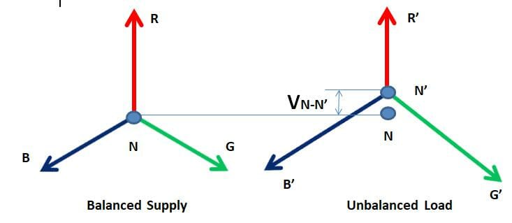
When supply neutral and load neutral are not in same potential then neutral current starts flowing through the neutral conductor. This neutral shifting can appear if either supply is not balanced against balanced load or load distribution is not equal among three phases, even when supply is properly balanced. Fig.2 shows the case of actual situation of the case study where it is found that it is the load which creates problem of neutral shifting. Vn-n’ is the imbalance voltage creating harmonics and large current through neutral conductor.

2. Harmonic distortion
As mentioned earlier, current imbalance creates harmonics. When
a solidly grounded system gets unbalanced, it generates third harmonics in neutral, as it
is a solidly grounded system. Every commercial building supply has to be 4-wire three
phase supply. Presence of triple harmonics generates conductor heating, proximity
noise, and communication interference.
3. Burn-out of single phase loads (lighting, power adapters etc.)
When the amount of imbalance in a particular phase is excessively high then the voltage imbalance will keep on increasing. For example, a power adaptor on a single phase load like a laptop/mobile/router or even fan/light can be damaged by a sudden surge of voltage. The problem could be more devastating if the sudden load transient occurred with an initial voltage imbalance.
4. Abnormal vibration, magnetic field distortion and coil heating in induction motors
For rotating machine like induction motors, running from a supply where supply neutral is not placed where it was supposed to, the motor magnetic coil inside will feel some magnetic imbalance due to the presence of a supply imbalance. If the motor is running in Delta (without supply neutral being connected to motor neutral), then the supply voltage imbalance will only effect its coil, giving rise to unwanted heating of the coil. Magnetic imbalance will try to create some abnormal vibration too.
If motor is running in STAR (supply neutral is connected to motor neutral), then the harmonics problem can be even more dangerous because there be a voltage imbalance which will try and create a magnetic imbalance. But a current imbalance (third harmonic will flow through neutral) will also intensify the situation.
In both instances, the machine has to sustain line harmonics coming from a power supply. These unwanted harmonics heat up motor coils. A heated coil will rapture the polymer coating of the coil and eventually, creates a coil having multiple local loops which weaken and distort the magnetic field. Table 1 shows the experimental result of a stator winding temperature rise. Resistance is measured using a digital multi-meter (Model RISH multi 15 S).
Table 1 shows the experimental result of a stator winding temperature rise. Resistance is measured using a digital multi-meter (Model RISH multi 15 S)
Table 1. Effect of unbalance on motor winding resistance

Load imbalance and harmonics in a commercial building
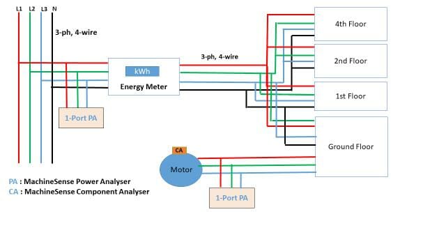
This case study was performed on a standard commercial building to study the effect of load imbalance and nonlinear loads on current imbalance, harmonic distortion, and coil properties of induction motors. Fig. 1 show the building layout.


- Motor
- MachineSense Power Toroid
- MachineSense Component Analyzer
- MachineSense Power Analyzer
- MachineSense Datahub
- Router
- Cloud Based Server
- MachineSense Crystalball portal
- MachineSense Dataviewer App
- MachineSense MRO in email
- MachineSense MRO in sms
Experimental Set-Up
- Current imbalance, voltage imbalance, harmonics, and motor winding resistance with and without load imbalance.
- Current imbalance, voltage imbalance, harmonics, and motor winding resistance with and without nonlinear devices such as SMPS connected to the system.


Note: Fig. 4/5/6 shows the plot of actual raw data collected by MachineSense Power Analyzer during the experiment (day vs night). Raw data downloaded from the server and then simply plotted in Excel.
Real time Data viewer of MachineSense Power Analyzer

Observation & Conclusion
MachineSense Power Analyzer (PA) captures the real problem happening in the standard commercial building. At daytime, between 1 PM to 4:30PM when the motor was running with days of imbalance problems, MachineSense PA detected high current THD around more than 15% at the motor input terminal, whereas when the same motor was running at night time, between 6:30PM to 9PM, PA detected current THD around less than 10%. It is clearly indicating the impact of a daytime THD problem.
This is mainly due to several factors including improper load distribution, load- in building– which mostly runs throughout day– large number of the SMPS/power adapter– running parallel etc. But at night time, around 6:00PM to 6:30PM, when almost 80% of load are turned off, the impact is considerably less than at daytime.
MachineSense Power Analyzer (PA) has proven to be extremely useful in this case to detect the problems, which can be analysed and provide preventative measures to help avoid future issues.

MachineSense Power Analyzer (PA) also captures the real problem of current imbalances, happening in a commercial building currently under consideration, at daytime hours. MachineSense PA detected high current imbalance of almost more than 50% at the input feeder side where the main supply enters into the building. Once the MachineSense Power Analyzer was connected at the Main incoming DB to detect the whole building load distribution, current THD etc., the reading were helpful in detecting anomalies that could cause problems.
This large current imbalance at daytime may result short circuit, or burning the neutral conductor due to high neutral imbalance current passing through it.
MachineSense Power Analyzer was very useful in this case study to detect the problem.
Appendix-1
To detect the temperature rise of the winding, MachineSense Component Analyzer (CA)was used. It was placed on top of the machine along with the one Power Analyzer.
Table 1 shows that cold resistance of the winding is around 4.44 ohm at 31 deg C. When machine was running at daytime we found the rise in resistance is 0.43, 0.2,0.2 in ohm respectively in L1, L2, L3.

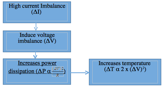
Using a standard temperature co-efficient formula we found a maximum rise in temperature of 25.7 degrees C in L1 at day time. When the same motor was running at night we found a rise in temperature of 8 degrees C. This is because of two main reasons: One is line harmonics injected by supply at daytime hours; and another is voltage imbalance induced by the current imbalance at daytime.

For machine, winding temperature rise due to voltage imbalance is calculated by the following equation.
% ΔT = 2 x { (ΔV)2}
Where ΔV is the voltage imbalance.
So only a 2% voltage imbalance may lead to 8% temperature rise in motor winding.

